US3441214A - Method and apparatus for seeding clouds - Google Patents
Method and apparatus for seeding clouds Download PDFInfo
- Publication number
- US3441214A US3441214A US607970A US3441214DA US3441214A US 3441214 A US3441214 A US 3441214A US 607970 A US607970 A US 607970A US 3441214D A US3441214D A US 3441214DA US 3441214 A US3441214 A US 3441214A
- Authority
- US
- United States
- Prior art keywords
- explosive
- cloud
- package
- casing
- cord
- Prior art date
- Legal status (The legal status is an assumption and is not a legal conclusion. Google has not performed a legal analysis and makes no representation as to the accuracy of the status listed.)
- Expired - Lifetime
Links
Images
Classifications
-
- A—HUMAN NECESSITIES
- A01—AGRICULTURE; FORESTRY; ANIMAL HUSBANDRY; HUNTING; TRAPPING; FISHING
- A01G—HORTICULTURE; CULTIVATION OF VEGETABLES, FLOWERS, RICE, FRUIT, VINES, HOPS OR SEAWEED; FORESTRY; WATERING
- A01G15/00—Devices or methods for influencing weather conditions
Definitions
- the invention relates to the seeding of clouds and particularly to a safe method and apparatus for seeding clouds from an aircraft when using an ice-nucleating material generator of an explosive nature.
- the present invention aims to provide a method and apparatus for seeding clouds when using explosive-type generators.
- a package containing the explosive generator from an aircraft at a predetermined distance above the target cloud.
- the package includes a casing, an elongated explosive cord-like member, containing dispersed silver iodide, arranged about the exterior of the casing with at least one of its ends protruding within the casing; a plurality of detonator devices attached to the end of the cord-like member, a time fuse connected to each detonator device and having a delay determined by the distance the package is to be dropped, each time fuse being provided with an igniter including an actuator extending outside the casing.
- the package is ejected from an aircraft at a predetermined distance above the cloud to be seeded and simultaneously the actuator is actuated thereby igniting the time fuse and subsequently the detonating devices for detonating the explosive cord-like member.
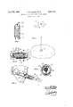
- FIGURE 1 is a perspective view of the package to be dropped
- FIGURE 2 is a cross-sectional view taken along the central axis
- FIGURE 3 is a cross-sectional view taken along line 33 of FIGURE 2;
- FIGURE 4 is a fragmentary view showing the package being ejected from an aircraft
- FIGURE 5 is a diagrammatic view illustrating the seeding of clouds according to the present invention.
- the package containing an explosive generator is generally identified by the numeral 10.
- the package 10 includes a tubular casing 12 which in this case is made of a strong paperboard material.
- Each end of the tubular casing 12 is provided with a suitable cap 14 and 16.
- Cap 14 is provided with a central aperture 18.
- a cord-like explosive member 20 is coiled about the exterior wall of casing 12. The ends of the explosive member 20 pass through apertures 22 and 24 into the interior of casing 12.
- the cord-like explosive member 20 is preferably of the type described in US. Patent 3,127,107 and contains approximately 3.2 gm. of PETN (pentaerythritol tetranitrate) and 0.8 gm. of AgI per foot of cord. It detonates at a velocity of about 18,000 ft. sec.
- the blasting caps 26, 27 and 28 are attached to the ends of the member 20 by a piece of string.
- the blasting caps 26, 27 and 28 are connected to black powder fuses 30, 31 and 32 respectively.
- the individual lengths of fuses 30, 31 and 32 determine the delay for detonating the charge after ejection.
- the free ends of the fuses 30, 31 and 32 are connected with standard pull-wire igniters 34, 35 and 36 respectively.
- the pull wires 38, 39 and 40 extend through the aperture 18 and are connected to a single lanyard 42. It is understood that for safety purposes the detonating device including the blasting caps are only connected to the ends of the cord-like explosive member when the package 10 is being readied for ejection.
- the aircraft 44 from which the package 10 is to be ejected is provided with a barrel 46 protruding through the side wall of the aircraft behind or below the wing.
- the approximate height at which the aircraft will fiy over the cloud is first determined and the fuses 30, 31 and 32 are cut to a length corresponding proportionally to the time delay required for free fall at that predetermined height.
- the blasting caps 26, 27 and 28 are then crimped to the end of the fuses 30, 31 and 32 and the complete detonating device including the blasting caps, fuse and pull wire igniter is inserted within the casing 12 while at the same time attaching the blasting caps 26, 27 and 28 to the ends of cord-like explosive member 20.
- the end cap 14 is then secured to the rim of the casing 12 with pull wires 38', 39 and 40 extending through the aperture 18 and attached to the lanyard 42.
- the completed package 10 is then placed in a barrel 46 and the lanyard is attached to a fixed member 48 in the aircraft.
- a push member 50 of the type shown in FIGURE 4 is then applied with pressure to the end of the package 10 to eject the package 10 from the barrel 46.
- the action of ejecting the package 10 causes the lanyard 42 to pull the pull wires 38, 39 and 40 thus activating the pull wire igniters 34, 35 and 36 in order to light the fuses 30, 31 and 32.
- the fuses burn until the blasting caps 26, 27 and 28 are reached whereby the explosive charge is detonated.
- the silver iodide dispersed in the explosive cord-like member 20 is distributed in the cloud in order to form ice-generating nuclei.
- An important safety feature of the package 10 is that at least three independent detonating devices are used.
- a method of cloud seeding comprising the steps of flying over a cloud to be seeded at a given distance from the cloud in an aircraft, placing an explosive body containing dispersed ice-nucleating materials connected to a plurality of time-detonating fuses in an ejection zone outside of the aircraft body, coordinating the time fuse to said given distance, ejecting said explosive body while simultaneously initiating the ignition of each time fuse as the explosive body is ejected from the ejection zone outside of the aircraft body thereby causing the detonation of the explosive member in said cloud to release the ice-nucleating materials in the cloud.
- An apparatus for seeding clouds comprising an aircraft body, an ejection tube extending outwardly of the body and communicating therewith, anchor means within the aircraft adjacent said ejection tube, a tubular casing,
- a cord-like explosive member containing dispersed ice-nucleating materials suitable for insertion within the ejection tube at least a portion of said cord-like explosive member extending within said casing, a plurality of detonating devices attached to the portion of the cord-like member extending Within the casing, for detonating the cord-like member, a separate time fuse connected to each detonating device, a plurality of self-igniting means each attached to one of said time fuses for individually igniting the time fuses when activated, and a detachable activating means connected to each of said self-igniting means extending outward of said casing and being adapted for attachment to said anchor means when the casing is Within the ejection tube, whereby the time fuses are ignited as the casing is ejected from the ejection tube.
- An apparatus as defined in claim 2 wherein the explosive cord-like member has a core of de-sensitized pentaerythritol tetranitrate and a protective sheath about said core, said core also containing from 3.5% to about 20% by weight of silver iodide.
- time fuse is of the black powder type and there is one fuse independently connected to each blasting cap.
Description
Aprilzg, 1969 J. D'AVIGNON ET 3,441,214
METHOD AND APPARATUS FOR SEEDING CLOUDS Filed Jan. 9, 1967 INVENTOR Bernard Allan POWER Jacques d'AVlGNON ATTORNEY United States Patent US. Cl. 2392 6 Claims ABSTRACT OF THE DISCLOSURE An apparatus and method for seeding clouds from an alrcraft by means of a package including an explosive generator containing silver iodide. The package also includes a time fuse attached at one end to an igniter and at the other end to a detonator for setting off the fuse cord containing the silver iodide at the required height.
BACKGROUND OF THE INVENTION The invention relates to the seeding of clouds and particularly to a safe method and apparatus for seeding clouds from an aircraft when using an ice-nucleating material generator of an explosive nature.
Since the developments of V. Schaefer and B. Vonnegut with respect to cloud seeding by introducing into the clouds, crystals of material foreign with respect to the clouds and having a space group and unit cell dimensions closely approximating those of ice crystals, which act as nuclei for the formation of ice crystals within the clouds, as disclosed in U.S. Patents 3,527,230 and 2,527,231, many attempts have been made to improve the efficiency of such cloud seeding. For instance, burner generators have been pro-posed, by which it is carried by aircr'afts through clouds. However, the concentration of nuclei per unit volume when using such generators is very low.
On the other hand, an explosive type generator has now been developed such as is described in US. Patent 3,127,107, Merryweather, 1964, which has a very high concentration of AgI in a very small volume. It is noted, however, that the explosive-type generator cannot normally be handled or seeded in clouds by conventional methods.
The present invention aims to provide a method and apparatus for seeding clouds when using explosive-type generators.
In accordance with the present invention, it is proposed to drop a package containing the explosive generator from an aircraft at a predetermined distance above the target cloud. The package includes a casing, an elongated explosive cord-like member, containing dispersed silver iodide, arranged about the exterior of the casing with at least one of its ends protruding within the casing; a plurality of detonator devices attached to the end of the cord-like member, a time fuse connected to each detonator device and having a delay determined by the distance the package is to be dropped, each time fuse being provided with an igniter including an actuator extending outside the casing.
The package is ejected from an aircraft at a predetermined distance above the cloud to be seeded and simultaneously the actuator is actuated thereby igniting the time fuse and subsequently the detonating devices for detonating the explosive cord-like member.
Having thus generally described the invention, the same will 'be explained in more detail with reference to the accompanying drawings and in which:
FIGURE 1 is a perspective view of the package to be dropped;
FIGURE 2 is a cross-sectional view taken along the central axis;
FIGURE 3 is a cross-sectional view taken along line 33 of FIGURE 2;
FIGURE 4 is a fragmentary view showing the package being ejected from an aircraft, and
FIGURE 5 is a diagrammatic view illustrating the seeding of clouds according to the present invention.
Referring to the drawings and specifically to FIGURES 1, 2 and 3, the package containing an explosive generator is generally identified by the numeral 10. The package 10 includes a tubular casing 12 which in this case is made of a strong paperboard material. Each end of the tubular casing 12 is provided with a suitable cap 14 and 16. Cap 14 is provided with a central aperture 18.
A cord-like explosive member 20 is coiled about the exterior wall of casing 12. The ends of the explosive member 20 pass through apertures 22 and 24 into the interior of casing 12. The cord-like explosive member 20 is preferably of the type described in US. Patent 3,127,107 and contains approximately 3.2 gm. of PETN (pentaerythritol tetranitrate) and 0.8 gm. of AgI per foot of cord. It detonates at a velocity of about 18,000 ft. sec.
Three No. 6 blasting caps 26, 27 and 28 are attached to the ends of the member 20 by a piece of string. The blasting caps 26, 27 and 28 are connected to black powder fuses 30, 31 and 32 respectively. The individual lengths of fuses 30, 31 and 32 determine the delay for detonating the charge after ejection. The free ends of the fuses 30, 31 and 32 are connected with standard pull- wire igniters 34, 35 and 36 respectively. The pull wires 38, 39 and 40 extend through the aperture 18 and are connected to a single lanyard 42. It is understood that for safety purposes the detonating device including the blasting caps are only connected to the ends of the cord-like explosive member when the package 10 is being readied for ejection.
The aircraft 44 from which the package 10 is to be ejected is provided with a barrel 46 protruding through the side wall of the aircraft behind or below the wing.
When it is desired to seed a cloud from an aircraft 44 with the above-described explosive generator, the approximate height at which the aircraft will fiy over the cloud is first determined and the fuses 30, 31 and 32 are cut to a length corresponding proportionally to the time delay required for free fall at that predetermined height. The blasting caps 26, 27 and 28 are then crimped to the end of the fuses 30, 31 and 32 and the complete detonating device including the blasting caps, fuse and pull wire igniter is inserted within the casing 12 while at the same time attaching the blasting caps 26, 27 and 28 to the ends of cord-like explosive member 20. The end cap 14 is then secured to the rim of the casing 12 with pull wires 38', 39 and 40 extending through the aperture 18 and attached to the lanyard 42. The completed package 10 is then placed in a barrel 46 and the lanyard is attached to a fixed member 48 in the aircraft. A push member 50 of the type shown in FIGURE 4 is then applied with pressure to the end of the package 10 to eject the package 10 from the barrel 46. The action of ejecting the package 10 causes the lanyard 42 to pull the pull wires 38, 39 and 40 thus activating the pull wire igniters 34, 35 and 36 in order to light the fuses 30, 31 and 32. As the package 10 falls freely through the air, as shown in FIG- URE 5, the fuses burn until the blasting caps 26, 27 and 28 are reached whereby the explosive charge is detonated. Thus, the silver iodide dispersed in the explosive cord-like member 20 is distributed in the cloud in order to form ice-generating nuclei.
An important safety feature of the package 10 is that at least three independent detonating devices are used.
3 Therefore, if one igniter, fuse or blasting cap is defective, the others can still detonate the charge. Of course, the more independent detonating arrangements used, the greater the safety factor.
Detonator, 3 N0. 6 blasting caps.
Ground observations vertified that the detonation occurred at the proper predicted height within the cloud.
Five minutes after detonation, the top of the cloud was seen to increase in height, some 500' feet, and a changeover of the cloud composition from supercooled Water droplets to ice crystals was observed visually, according to the usual visual criteria for such a change, i.e., softening in the appearance of the outline of the cloud and general fuzziness developing in the cloud mass, etc. This verified that the silver iodide released by the detonation had operated to convert the supercooled portion of the cloud to ice crystals.
We claim:
1. A method of cloud seeding comprising the steps of flying over a cloud to be seeded at a given distance from the cloud in an aircraft, placing an explosive body containing dispersed ice-nucleating materials connected to a plurality of time-detonating fuses in an ejection zone outside of the aircraft body, coordinating the time fuse to said given distance, ejecting said explosive body while simultaneously initiating the ignition of each time fuse as the explosive body is ejected from the ejection zone outside of the aircraft body thereby causing the detonation of the explosive member in said cloud to release the ice-nucleating materials in the cloud.
2. An apparatus for seeding clouds comprising an aircraft body, an ejection tube extending outwardly of the body and communicating therewith, anchor means within the aircraft adjacent said ejection tube, a tubular casing,
about which is wrapped a cord-like explosive member containing dispersed ice-nucleating materials suitable for insertion within the ejection tube; at least a portion of said cord-like explosive member extending within said casing, a plurality of detonating devices attached to the portion of the cord-like member extending Within the casing, for detonating the cord-like member, a separate time fuse connected to each detonating device, a plurality of self-igniting means each attached to one of said time fuses for individually igniting the time fuses when activated, and a detachable activating means connected to each of said self-igniting means extending outward of said casing and being adapted for attachment to said anchor means when the casing is Within the ejection tube, whereby the time fuses are ignited as the casing is ejected from the ejection tube.
3. An apparatus as defined in claim 2 wherein the explosive cord-like member has a core of de-sensitized pentaerythritol tetranitrate and a protective sheath about said core, said core also containing from 3.5% to about 20% by weight of silver iodide.
4-. An apparatus as defined in claim 2 wherein there are three detonating devices, the detonating devices are No. 6 blasting caps and there are three time fuses, one to each blasting cap and three self-igniting means, one connected to each fuse.
5. An apparatus as defined in claim 3 wherein the time fuse is of the black powder type and there is one fuse independently connected to each blasting cap.
'6. An apparatus as defined in claim 4- wherein the self-igniting means is a pull-wire igniter and there is one connected independently to each fuse, and the actuator is the pull-wire from the pull-wire igniter extending through the end of the casing and attached to a lanyard adapted to be anchored.
References Cited UNITED STATES PATENTS 2,073,416 3/1937 Finzi 169-28 2,405,085 7/ 1946 Zappone 10 2-856 2,450,569 10/1948 Thompson 169-28 3,127,107 3/1964 Merryweather 239-2 EVERETT W. KIRBY, Primary Examiner.
US. Cl. X.R. 239-14; 169-28, 36; 102-6; 89-1
Applications Claiming Priority (1)
| Application Number | Priority Date | Filing Date | Title |
|---|---|---|---|
| US60797067A | 1967-01-09 | 1967-01-09 |
Publications (1)
| Publication Number | Publication Date |
|---|---|
| US3441214A true US3441214A (en) | 1969-04-29 |
Family
ID=24434473
Family Applications (1)
| Application Number | Title | Priority Date | Filing Date |
|---|---|---|---|
| US607970A Expired - Lifetime US3441214A (en) | 1967-01-09 | 1967-01-09 | Method and apparatus for seeding clouds |
Country Status (1)
| Country | Link |
|---|---|
| US (1) | US3441214A (en) |
Cited By (6)
| Publication number | Priority date | Publication date | Assignee | Title |
|---|---|---|---|---|
| US3717097A (en) * | 1969-11-21 | 1973-02-20 | Us Navy | Implosion colored marker |
| US3976008A (en) * | 1975-02-19 | 1976-08-24 | The United States Of America As Represented By The Secretary Of The Army | Pyrotechnic seeding pellet |
| US5357865A (en) * | 1991-02-22 | 1994-10-25 | Water Research Commission | Method of cloud seeding |
| US6056203A (en) * | 1996-12-15 | 2000-05-02 | Fukuta; Norihiko | Method and apparatus for modifying supercooled clouds |
| US20170217586A1 (en) * | 2016-01-29 | 2017-08-03 | JG Entrepreneurial Enterprises LLC | Aeronautical car and associated features |
| CN109310056A (en) * | 2016-01-29 | 2019-02-05 | Jg创业企业有限责任公司 | The aircraft and system changed for weather |
Citations (4)
| Publication number | Priority date | Publication date | Assignee | Title |
|---|---|---|---|---|
| US2073416A (en) * | 1935-03-18 | 1937-03-09 | Finzi Gino | Fire extinguishing grenade |
| US2405085A (en) * | 1943-04-06 | 1946-07-30 | Paragon Mfg Company | Ammunition time fuse |
| US2450569A (en) * | 1946-06-28 | 1948-10-05 | Factory Mutual Res Corp | Fire extinguisher |
| US3127107A (en) * | 1964-03-31 | Generation of ice-nucleating crystal |
-
1967
- 1967-01-09 US US607970A patent/US3441214A/en not_active Expired - Lifetime
Patent Citations (4)
| Publication number | Priority date | Publication date | Assignee | Title |
|---|---|---|---|---|
| US3127107A (en) * | 1964-03-31 | Generation of ice-nucleating crystal | ||
| US2073416A (en) * | 1935-03-18 | 1937-03-09 | Finzi Gino | Fire extinguishing grenade |
| US2405085A (en) * | 1943-04-06 | 1946-07-30 | Paragon Mfg Company | Ammunition time fuse |
| US2450569A (en) * | 1946-06-28 | 1948-10-05 | Factory Mutual Res Corp | Fire extinguisher |
Cited By (11)
| Publication number | Priority date | Publication date | Assignee | Title |
|---|---|---|---|---|
| US3717097A (en) * | 1969-11-21 | 1973-02-20 | Us Navy | Implosion colored marker |
| US3976008A (en) * | 1975-02-19 | 1976-08-24 | The United States Of America As Represented By The Secretary Of The Army | Pyrotechnic seeding pellet |
| US5357865A (en) * | 1991-02-22 | 1994-10-25 | Water Research Commission | Method of cloud seeding |
| US6056203A (en) * | 1996-12-15 | 2000-05-02 | Fukuta; Norihiko | Method and apparatus for modifying supercooled clouds |
| US20170217586A1 (en) * | 2016-01-29 | 2017-08-03 | JG Entrepreneurial Enterprises LLC | Aeronautical car and associated features |
| CN109310056A (en) * | 2016-01-29 | 2019-02-05 | Jg创业企业有限责任公司 | The aircraft and system changed for weather |
| EP3407703A4 (en) * | 2016-01-29 | 2019-11-20 | JG Entrepreneurial Enterprises LLC | Vehicles and systems for weather modification |
| US10787256B2 (en) * | 2016-01-29 | 2020-09-29 | Lta Corporation | Aeronautical car and associated features |
| US11420739B2 (en) * | 2016-01-29 | 2022-08-23 | JG Entrepreneurial Enterprises LLC | Aeronautical car and associated features |
| US20220355925A1 (en) * | 2016-01-29 | 2022-11-10 | JG Entrepreneurial Enterprises LLC | Aeronautical car and associated features |
| US11713115B2 (en) * | 2016-01-29 | 2023-08-01 | JG Entrepreneurial Enterprises LLC | Aeronautical car and associated features |
Similar Documents
| Publication | Publication Date | Title |
|---|---|---|
| US5386781A (en) | Parachute deployment system | |
| US4651648A (en) | Pyrotechnic aircraft carried bomb | |
| US4069762A (en) | Emissive decoys | |
| US3911823A (en) | Pyrotechnic devices | |
| US2742856A (en) | Burster | |
| US4132169A (en) | Fuel-air type bomb | |
| US3441214A (en) | Method and apparatus for seeding clouds | |
| US9879953B2 (en) | Firework accomodating apparatus comprising guide rod, firework and electronic unit | |
| US3431852A (en) | Position marker | |
| US4141294A (en) | Fuel-air type bomb | |
| US3135204A (en) | Means for explosively removing the nose cone of a missile | |
| US3478687A (en) | Very low descent rate,high intensity,illuminating flare | |
| EP0220228B1 (en) | Smoke grenade | |
| US2826990A (en) | Aerial sown grenade | |
| US2269900A (en) | Aerial mine and projectile | |
| US4132170A (en) | Fuel-air type bomb | |
| US1295213A (en) | Multiple submarine-destroyer. | |
| JP3347499B2 (en) | Explosive devices and fire bombs | |
| US3114317A (en) | Model rocket | |
| US2180667A (en) | Parachute signal | |
| RU2060002C1 (en) | Antihail rocket | |
| CN214912849U (en) | Aviation fire-fighting extinguishing device | |
| GB1337643A (en) | Warheads | |
| RU2105947C1 (en) | Cartridge for stimulation of atmospheric precipitation | |
| US1335406A (en) | Projectile |